1. Introduction
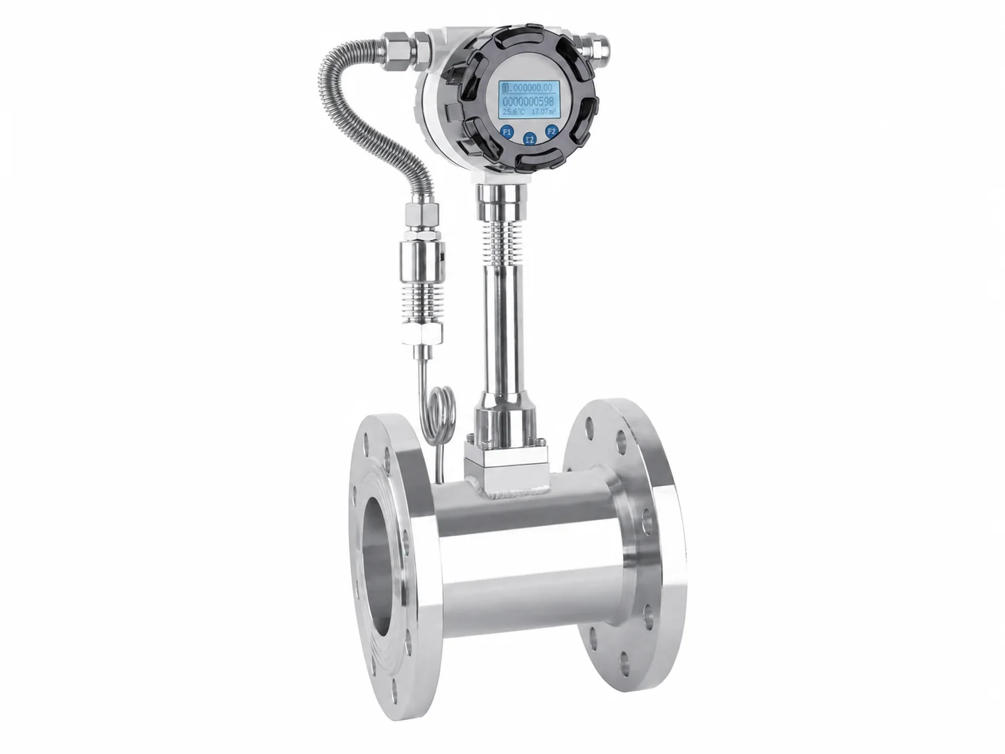
Vortex flowmeters are widely used in industrial process control due to their simple structure, low pressure loss, wide turndown ratio, and suitability for various gases, liquids, and steam. However, improper selection often leads to measurement deviation, vibration interference, or instrument damage. Based on industry-standard technical principles and standards (such as GB/T 20727, ISO 20456), this article systematically elaborates on the key points of vortex flowmeter selection.
2. Working Principle and Key Characteristics
The vortex flowmeter is based on the Karman vortex street principle: when fluid flows past a non-streamlined bluff body, vortices are alternately generated on both sides. The vortex frequency f is proportional to the flow velocity v, satisfying f = St · v / d, where St is the Strouhal number (constant within a specific Reynolds number range) and d is the characteristic dimension of the bluff body. The vortex frequency is detected by piezoelectric or capacitive sensors to derive the volumetric flow rate. This principle determines that the selection must focus on Reynolds number range, fluid velocity, and pipeline conditions.
3. Key Selection Parameters
3.1 Medium Characteristics
- Phase and Composition: Confirm whether the medium is gas, liquid, or steam, and whether multiphase flow exists. Vortex flowmeters are accurate for single-phase flow; caution is needed for bubbles or solid particles, and anti-erosion or special coating models may be required.
- Temperature and Pressure: Determine the operating temperature and pressure range, and select a sensor with appropriate temperature and pressure ratings (e.g., -40°C to +350°C, maximum pressure rating PN40 or Class300). High-temperature and high-pressure conditions require consideration of thermal expansion and sealing materials.
- Corrosivity and Viscosity: Corrosive media require corrosion-resistant materials (e.g., 316L stainless steel, Hastelloy). Viscosity affects the Reynolds number; high-viscosity fluids may push the meter into a nonlinear region.
3.2 Pipeline Conditions
- Nominal Diameter: Vortex flowmeters typically cover DN15 to DN300; larger diameters can use insertion or reduced-diameter designs. The selected size must match the pipe inner diameter to ensure sufficient straight pipe length.
- Straight Pipe Requirements: At least 10D upstream and 5D downstream (D = pipe inner diameter); longer lengths are needed if valves or elbows are present. Refer to GB/T 20727-2006.
- Vibration and Installation: Avoid installation in strong vibration locations; add vibration-damping supports if necessary. Horizontal or vertical installation is acceptable, but vertical installation should have upward flow.
3.3 Flow Range and Turndown Ratio
The turndown ratio of vortex flowmeters is typically 10:1 to 20:1, depending on the medium and diameter. The normal flow should be within 50% to 80% of the full scale, and the minimum flow should not be lower than the measurable lower limit (corresponding to Re ≥ 2×10^4). For gas measurement, compressibility must be considered, and standard volumetric flow is often used. Example: For a DN80 vortex flowmeter, liquid velocity range 0.5–6 m/s, gas velocity range 5–60 m/s.
3.4 Accuracy Level
Industrial vortex flowmeters typically have an accuracy of ±1.0% to ±1.5% of reading (liquid) and ±1.5% to ±2.0% of reading (gas); high-accuracy models can achieve ±0.75%. The selection should meet process requirements; for custody transfer, higher accuracy and regular calibration are needed.
3.5 Output and Communication
Common outputs include 4-20mA analog, pulse frequency, or RS485 digital communication (Modbus protocol). The selected output must be compatible with the DCS/PLC system, and considerations for remote transmission distance and explosion-proof requirements (e.g., intrinsic safety Ex ia or flameproof Ex d) are necessary.
4. Selection Procedure and Example
Take a chemical plant's steam flow measurement as an example: medium is saturated steam, temperature 180°C, pressure 1.0MPa, pipe DN100, normal flow 5 t/h. Steam density is approximately 5.5 kg/m³, volumetric flow is about 909 m³/h, velocity about 32 m/s (within the recommended gas range). Select a DN100 vortex flowmeter rated for 250°C and 1.6MPa, with 4-20mA output, material 316L. Install with 12D upstream and 6D downstream straight pipe, and add pipe supports.
5. Common Problems and Solutions
- Vibration Interference: Use sensors with vibration compensation or adjust the installation location.
- Inaccurate Low Flow Measurement: Use a reducer to increase velocity or select a smaller diameter meter.
- Dirty Medium: Clean periodically or choose a model with purge function.
6. Conclusion
Vortex flowmeter selection requires comprehensive consideration of medium properties, pipeline conditions, process parameters, and environmental factors. Follow the principle of 'calculate first, select later, prioritize installation for accuracy.' It is recommended to communicate fully with the instrument supplier (such as Jiangsu SIENCUN Instrument Co., Ltd.) before selection, providing detailed operating conditions, and conduct on-site verification if necessary.