1. Introduction
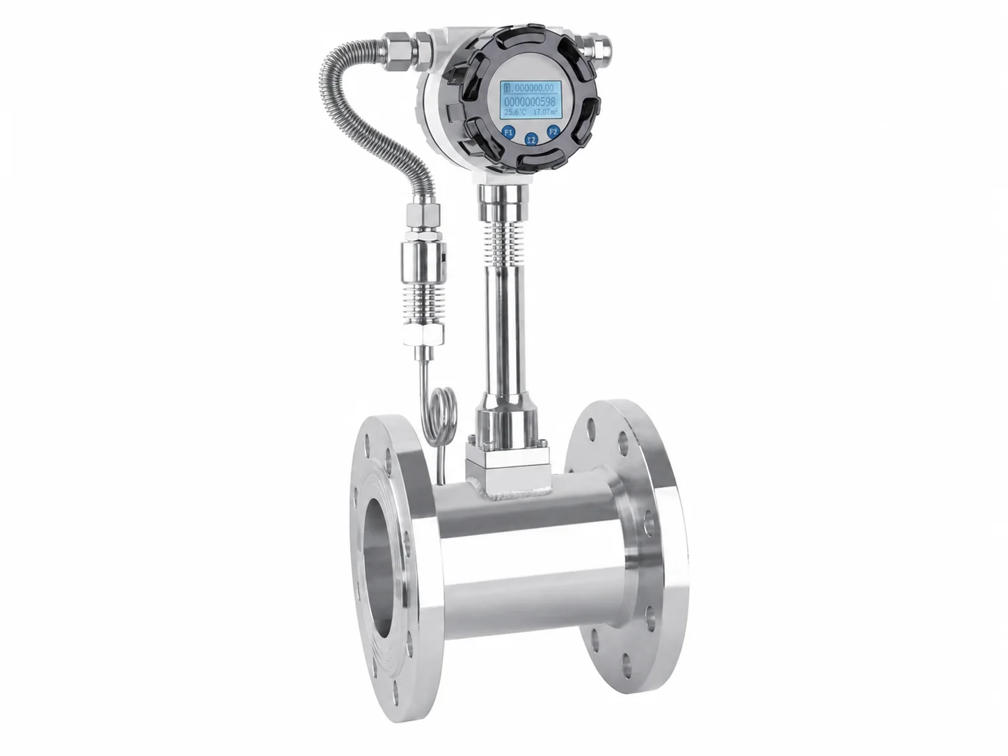
Steam, as an important secondary energy source, is widely used in industries such as chemical, power, and pharmaceutical. Vortex flowmeters are commonly used for steam measurement due to their simple structure, wide rangeability, and low pressure loss. However, the special physical properties of steam—high temperature, high pressure, and easy phase change—often cause problems such as inaccurate measurement and unstable signals. This article analyzes common problems and proposes countermeasures based on industry technical principles and standards.
2. Working Principle of Vortex Flowmeter
The vortex flowmeter is based on the Kármán vortex street principle: a non-streamlined bluff body is placed in the fluid. When fluid flows past it, alternating vortices are shed from both sides. The shedding frequency is proportional to the flow velocity and inversely proportional to the characteristic width of the bluff body. By detecting the vortex frequency, the flow velocity can be obtained, and then the volumetric flow rate is calculated. For steam measurement, temperature and pressure sensors are usually required for density compensation to obtain mass flow rate.
3. Common Problems
3.1 Measurement Errors Due to Steam State Changes
Steam is classified as saturated steam and superheated steam, with density varying significantly with temperature and pressure. If the flowmeter uses a built-in fixed density value, or if temperature/pressure compensation is not timely or accurate, large mass flow errors will occur. Additionally, steam may partially condense during transportation due to heat loss, forming two-phase flow (gas-liquid mixture). Vortex flowmeters are very sensitive to two-phase flow; liquid droplets can interfere with the vortex signal, causing abnormal frequency output.
3.2 Vibration Interference
Vortex flowmeters rely on detecting weak pressure pulsations or stress changes generated by vortices. Pipeline vibrations (e.g., from upstream valves, pumps, elbows) can superimpose on the signal, causing false triggering or signal distortion, especially at low flow rates (low frequencies).
3.3 Improper Installation Conditions
Vortex flowmeters require strict upstream and downstream straight pipe lengths: at least 10D upstream and 5D downstream (D is pipe diameter). Insufficient straight pipe leads to unstable flow patterns, preventing the generation of a stable vortex street. Additionally, installing downstream of a control valve or near large resistance components exacerbates flow field distortion.
3.4 Reynolds Number Limitations
Vortex flowmeters maintain linearity only within a certain Reynolds number range (typically Re≥2×10⁴). At low flow rates or high viscosity (e.g., wet steam), the Reynolds number may fall below the lower limit, causing the meter coefficient to change and measurement error to increase.
3.5 Sensor Scaling and Corrosion
Steam may contain impurities (e.g., rust, scale). Long-term operation can cause scaling on the bluff body and sensor surface, altering the geometric dimensions and affecting the relationship between vortex frequency and flow velocity. High-temperature steam can also accelerate corrosion, damaging the sensor.
4. Countermeasures and Recommendations
4.1 Proper Selection and Range Matching
Select the appropriate diameter of vortex flowmeter based on actual steam conditions (temperature, pressure, flow range). Ensure that the normal flow rate falls within 20% to 80% of the full scale, and the minimum flow rate is above the measurable lower limit (corresponding to the Reynolds number lower limit). For fluctuating conditions, choose a model with a wide rangeability.
4.2 Enhanced Temperature and Pressure Compensation
Use an integrated vortex flowmeter with temperature and pressure compensation, or connect external temperature and pressure transmitters for real-time density calculation. The compensation algorithm should be based on steam property tables (e.g., IAPWS-IF97) or fitting formulas to ensure accurate calculation in both saturated and superheated steam regions. Calibrate temperature and pressure sensors regularly.
4.3 Standardized Installation
Strictly follow installation standards: ensure sufficient straight pipe lengths, avoid mounting near vibration sources. If vibration is unavoidable, choose a vortex flowmeter with vibration compensation function, or use flexible connections and vibration dampers. For steam measurement, it is recommended to install the flowmeter on a vertical pipe with upward flow to facilitate condensate drainage.
4.4 Two-Phase Flow Handling
In steam pipeline design, install steam traps and moisture separators to reduce condensate entering the flowmeter. If two-phase flow is inevitable, consider using a dual-sensor vortex flowmeter or transition to other principles (e.g., differential pressure).
4.5 Signal Processing and Anti-Interference
Use digital signal processing (DSP) technology with bandpass filtering and adaptive thresholding to extract the true vortex frequency and suppress vibration and noise interference. Regularly inspect sensors and electronics, and clean the bluff body surface.
4.6 Regular Maintenance and Calibration
Establish a regular inspection schedule to check the flowmeter appearance, wiring, and display. Perform on-site or off-site calibration at least once a year using a standard flow facility (e.g., sonic nozzle) to verify the meter coefficient. For severe scaling, disassemble and clean.
5. Conclusion
Vortex flowmeters offer advantages in steam measurement, but their operating conditions must be respected. Through proper selection, standardized installation, enhanced temperature/pressure compensation and signal processing, and routine maintenance, measurement accuracy and reliability can be significantly improved. With advances in electronics and algorithms, the adaptability of vortex flowmeters in complex conditions will continue to increase.